

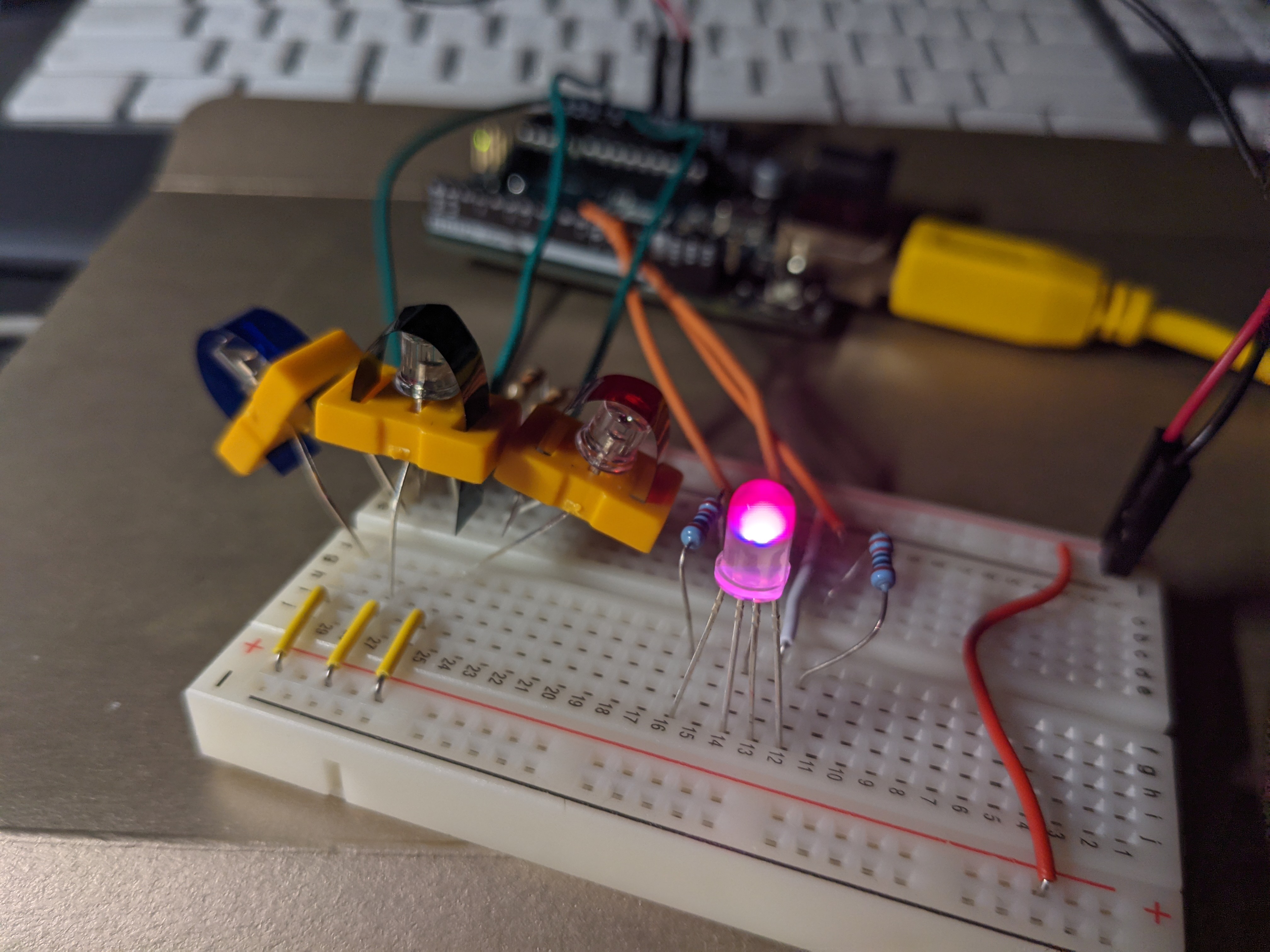
learning to use Pulse Width Modulation (PWM = Fancy!) to control the brightness and color of an LED since the Arduino Uno doesn’t have the ability to vary the amount of power that any of the pins supplies. The example in the starter kit uses light input and colored gels to filter light for each of the three phototransistors and selectively filter RGB and then print that value and divide by 4 to create a new value to supply the cathode RGB LED a value for each and control its color output.
/*

*/
const int greenLEDPin = 9;
const int redLEDPin = 10;
const int blueLEDPin = 11;

const int redSensorPin = A0;
const int greenSensorPin = A1;
const int blueSensorPin = A2;

int redValue = 0;
int greenValue = 0;
int blueValue = 0;

int redSensorValue = 0;
int greenSensorValue = 0;
int blueSensorValue = 0;


void setup() {
    Serial.begin(9600);

    pinMode (greenLEDPin, OUTPUT);
    pinMode (redLEDPin, OUTPUT);
    pinMode (blueLEDPin, OUTPUT);

}

void loop() {
  redSensorValue = analogRead(redSensorPin);
  delay (5);
  greenSensorValue = analogRead(greenSensorPin);
  delay (5);
  blueSensorValue = analogRead(blueSensorPin);
  Serial.print("Raw Sensor Values \t red: ");
  Serial.print(redSensorValue);
  Serial.print("\t green: ");
  Serial.print(greenSensorValue);
  Serial.print("\t blue: ");
  Serial.print(blueSensorValue);

  redValue = redSensorValue/4;
  greenValue = greenSensorValue/4;
  blueValue = blueSensorValue/4;

  Serial.print("Mapped Sensor Values \t red: ");
  Serial.print(redValue);
  Serial.print("\t green: ");
  Serial.print(greenValue);
  Serial.print("\t blue: ");
  Serial.print(blueValue);

  analogWrite(redLEDPin, redValue);
  analogWrite(greenLEDPin, greenValue);
  analogWrite(blueLEDPin, blueValue);

}
